


yxhtfmtv
YXHT FM STL Studio-Transmitter Link System for Radio Station
YXHT FM STL Studio-Transmitter Link System for Radio Station
Impossible de charger la disponibilité du service de retrait
DIGITAL STL TRANSMISSION SYSTEM
YXHT658

Service Manual
Please note:
1. Read the safety instructions first.
2. In front of the boot must meet 50 Ω dummy load or antenna and ensure the standing wave ratio is less than 1.30.
3. Read the system control logic to understand how the system is controlled and works.
4. Please read the boot sequence.
1. Summarize
The digital STL transmission system equipment is specialized for the wireless transmission of audio signals from the studio to the transmitter station.The equipment adopts the most advanced software radio (SDR) technology to transmit and receive the audio signal in the form of digital coding modulation, digital demodulation and decoding, which can realize the long distance transmission of the audio signal with very high quality and almost no damage.
The transmission distance of the STL system equipment is within 60 kilometers of the line-of-sight, and it can transmit the analog stereo along the way
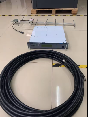
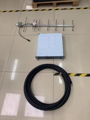
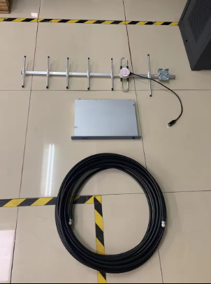
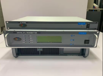
STL transmitter, transmitting filter, transmitting antenna feeder, receiving antenna feeder, STL receiver and other equipment.

Note: The antenna at the receiving end should not be too close to the antenna at the transmitting end (40-60km). The distance between STL transmitter and STL Receiver must be greater than 40KM when starting up, or it will cause DAMAGE to STL Receiver.
2. Performance Index
2.1 Technical Specifications
|
1. Receiving frequency range 2. Frequency stability 3. The output power 4. Shoulder 5. Stray outside the band 6. Modulation type 7. Receiving sensitivity
8. Audio input/output signal 9. Frequency response 10. Signal to noise ratio 11. The distortion degree of 12. Degree of separation 13. The power supply voltage |
100MHz~1000MHz Adjustable 2ppm 10W ≥37 <-80dBc QPSK@8M;32QAM@2M;32QAM@6M QPSK/-90dBm @83dB S/N; 32 QAM/-78dBm @83dB S/N Digital Audio AES/EBU ±0.2dB @30Hz~15000Hz,0dBm >63dB @1KHz,0dBm <0.05% @30Hz~15000Hz,0dBm >65dB @30Hz~15000Hz,0dBm AC90V~AC260V ,47Hz~63Hz |
2.2 Physical Property
|
1. Crate standards Transmitter Receiver 2. Case size Transmitter Receiver 3. Machine weight Transmitter Receiver 4. Operating environment temperature 5. Cooling Noise |
2U (38 inches) 1U (19 inches)
Width 440mm × height 88mm × depth 450mm Width 440mm × height 44mm × depth 300mm
23kg 4kg -10℃ ~ +50℃ Forced air cooling, three anti - treatment <50dB |

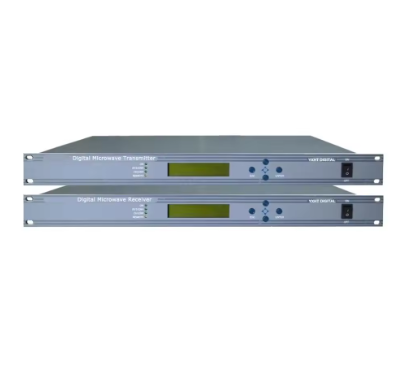
1 - Indicator light
ON indicator: Power indicator
RF indicator: radio frequency output indicator
DATA indicator: DATA transmission indicator
REMOTE control indicator
TEMP indicator: over-temperature indicator
VSER indicator: Standing wave ratio over-limit indicator
GENERAL indicator light: overvoltage, overcurrent, system fault alarm indicator light
RF MUTE light: Radio frequency prohibited indicator light
2 - LCD (Liquid Crystal Display)
3 - Button confirm
4 - Button up
5 - Button down
6 - Power switch
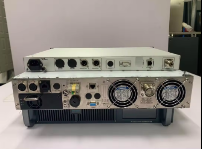
3.1.2 Back panel description

- Analog L audio input
2 - Analog R audio input
3 - Modulation board network port Settings (TCP/IP2)
4 - ASI input (optional)
5 - 220V AC input
6 - Parameter setting Communication port (TCP/IP)
7 - Parameter setting Communication port (232 ports)
8 - L27 RF output

1 - Power indicator light
2 - Power switch
3.3.2 Receiver installation Instructions

1 - Power socket
2 - Audio output station
3 - ASI OUT (optional)
4 - Reserved
5 - Parameter setting Communication port (TCP/IP)
6 - RF Input interface (Receiving antenna Interface)
3.4 Installation and connection
3.4.1 Transmitter installation
a) Open the package and check whether the appearance is damaged, and whether the switches, buttons, sockets and interfaces on the front and rear panels are in good condition;
b) Turn the power switch to "OFF" and connect the power cord to the AC power socket;
c) Please be sure to connect a 50Ω dummy load or antenna with a rated power not less than the transmitting power and a standing wave ratio less than 1.30;
d) Set the parameters and connect the TCP/IP communication port to the PC through a network cable;
e) Turn the power switch to "ON" to turn on;
f) Use the browser to use the network port to connect the device to complete the transmission power, transmission frequency, modulation mode, working bandwidth, and other parameter settings;
g) Turn on the radio frequency power.
3.4.2 Receiver installation instructions
a) Open the package and check whether the appearance is damaged, and whether the switches, buttons, sockets and interfaces on the front and rear panels are in good condition;
b) Turn the power switch to "OFF" and connect the power cord to the AC power socket;
c) Connect the parameter setting TCP/IP communication port to the PC through a network cable;
d) Turn the power switch to "ON" to turn on;
e) Use the browser to open and run the network connection device using the network port to complete the setting of the receiving frequency, demodulation method, working bandwidth, and other parameters.
3.4.4 System connection installation instructions
step one:
1. Connect the "parameter setting communication port" of the receiver to the PC through a network cable, and open the receiver parameter setting software with a browser.
2. Click on the FACTORY status page and observe the received signal-to-noise ratio (SNR) value.
3. When the SNR exceeds 18, the STL transceiver system is successfully connected.
4. Parameter setting software operating instructions
4.1 Overview
The main parameters of STL transmitter and receiver are set and observed through parameter setting software. After the PC computer is connected to the transmitter or receiver through a network cable, open the parameter setting software (specify the IP address) with a browser to configure and observe various parameters of the device.
The default IP addresses of STL transmitter and receiver are 192.168.1.150.
4.2 Transmitter software operation
Various browsers can be used to open the parameter setting software, such as IE (or WIN10 edge), Chrome, Firefox, etc., but the latest version is recommended for better compatibility.
Ø SYSTEM
The system parameter interface is shown in Figure 2. Click the lower triangle icon of the DEVICE (device type) option, select TX, select 3M in the BANDWIDTH option, and select QPSK in the MODULATION option.

Ø RF
The radio frequency parameter interface is shown in Figure 3. After changing the previous column, click the number in the TXFREQ option in RF to input the frequency to be transmitted, and input the level to be output in POWER (adjustment is not recommended, the factory has set it), the value before the value The inverted triangle icon can select positive and negative values.
Ø NMS
The network parameter interface is shown in Figure 4. The default device IP is 192.168.1.150. If you change the IP address through the web page, it will take effect immediately. After setting, enter the new IP address to access the web page.

4.3 Receiver software operating instructions
Ø SYSTEM
The system parameter interface is shown in Figure 2. Click the lower triangle icon of the DEVICE (device type) option, select RX, select 3M in the BANDWIDTH option, and select QPSK in the MODULATION option.
Ø RF
The radio frequency parameter interface is shown in Figure 3. After changing the previous column, click the number in the TXFREQ option in RF to enter the frequency to be received. The frequency of the receiver must be consistent with the frequency of the corresponding transmitter.